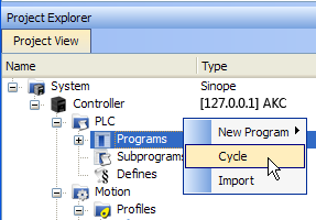
Define the PLC Cycle
The cycle specification defines the number of cycles between successive executions of the programs.
- In the Project Explorer, expand the PLC node and right-click on the Programs item to open the contextual menu and select the Cycle command
The Cycle window allows the regulation of the following parameters: Period and Phase.
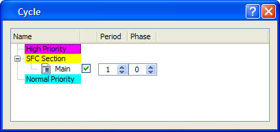
The cycle configuration dialog box is used to configure the programs priority into the Virtual Machine.
| Column | Description |
|---|---|
| Name |
List of PLC programs grouped together by priority level. The priority defines the order of execution. The SFC programs have a specific section as they must be grouped together. High Priority means "executed before SFC", and Low Priority means "executed after SFC". |
| Check box | Enables or disables the execution of the corresponding program. |
| Period |
Defines how many cycles are set between two executions of the program. You can define various sampling periods for programs of the
application. Default period is "1" (the program is executed on each cycle). |
| Phase |
Defines an offset that enables you to dispatch slow programs among few cycles. The goal of postponing the program execution is to reduce execution peak loads. Example: |
In the High and Normal Priority sections, adjust the order of the programs with a drag-and-drop operation according to the expected sequence. In each section, the program on the top is executed first.
Select the program you want to set with a higher priority, then drag and drop it to the relevant priority level.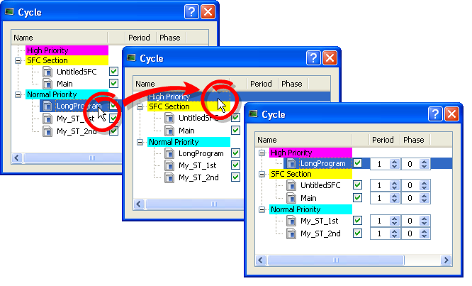
Figure 3: Change Priorities by Defining the Cycle
If all programs are with a Period set to 1, the KAS-IDE is more loaded. The choice of the Period for the programs gives you the possibility to distribute the load of the application.
also see "Tasking Model / Scheduling" on page 1 and Order of Execution.
Specify the Duration of a Cycle
This parameter is defined in EtherCAT Master Settings tab.
Ensuring Variables are Exported
Program Organization Units (POUs) which contain variables (see Map Variables to HMI) must be compiled for the variable to be exported.
Example: In these images, a POU (UntitledST) has two variables, NewVar and NewVar1.
- Only NewVar1 is set to be exported (1).
- The POU, however, is not set to be executed in the Cycle dialog box (2).
- This causes a compile error (3).
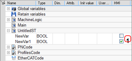
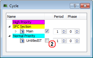
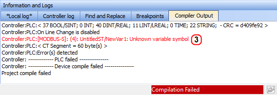
Figure 4: Example of a variable not being exported and the resulting compile error.


